February 10, 2021
Es season cometh! Time to build a 6M amplifier for my grid square outings based on a W6PQL pallet.
 |
| W6PQL pallets are usually available in kit form or assembled. |
I'm a big fan of KISS when building amps, that is "keep it simple stupid". I'm able to build these amps into a 12x8x3 inch chassis (Bud AC-424 chassis, BPA-1519 cover plate) with basic hand tools and a drill. I've not had much success using a power FET to switch the 50 vdc VDD line, so I use an old school mechanical relay. Ker-chunk! However, I do use the W6PQL FET module both to switch the low level 13.8 vdc with the PTT line from the radio to pull the VDD relay in, and to send 13.8 vdc to the bias input on the amp pallet going into transmit.
I do mount a small fan inside the chassis to move some air across the output bits, and a bigger fan runs atop the heatsink - both fans run continuously. The 6 Meter amp will be the seventh one I've built. Of course one can certainly add protective measures like over drive, over temperature, and high SWR lockouts, but then we've moved beyond KISS! Lest Murphy hear me I'll just whisper this, " I have yet to blow up one of these amps".
I use a check list 100% of the time to make sure I'm connected to an antenna, SWR is good, drive level set, and the PTT line activates before operating.
Over driving, or excessive heating will be what kills an LDMOS amp. Typically a shorted or open output line will blow up capacitors or vaporize the PCB traces and the device will survive.
Step 1 - laying the chassis
Take a perfectly good, factory fresh chassis and immediately hack a large hole in the top side for the RF pallet's heat-spreader to just fit. Layout and drill holes, lots of holes. I used blue painter's tape (since removed) to layout most of the holes. The pallet hasn't arrived so a few holes have to wait unit I see how the VDD feed and low pass filter will fall. The pallet's copper heat-spreader will be secured to the heatsink and then heatsink will bolt to the chassis. But that all waits for the support circuitry to be installed along the internal side walls first.
You can click on any of these pictures to expand to a larger size.
 |
| Lots of metal butchering on the 12x8x3 inch chassis. |
Step 2 - Mount supporting electronics
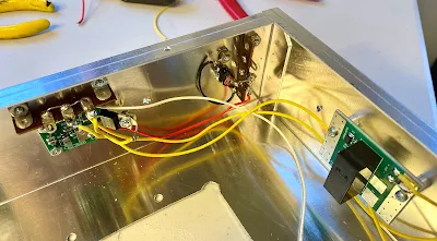
In the picture below you can see that on the back chassis wall near the input end wall I've mounted the 13.8 vdc input socket, and the switched 13.8 vdc logic board for relays and bias. On the input side wall I've mounted the RF input RX/TX relay. The RCA socket for the PTT, and BNC socket for the RF input are yet to be installed, but the pilot holes are there.
This is a 6 Meter amplifier, so antenna switching relays are internal unlike my 2M/70cm/23cm amps for EME that have a pre-amp, and the TX/RX relays out at the array feed point. You can see shoe-horning all the bits into the chassis takes some thought.
 | ||
| The leads haven't been dressed yet with tie wraps. Excuse my mess. :-) |
A long view showing the output RF relay, and the 50 volt VDD relay, I'm now waiting on a few parts before finishing off the support electronic wiring. The power relay is a $5.95 item from All Electronic with the contacts wired in parallel.
 |
| Five hours in, half way along. An RG-316 jumper installs between the RF relays. |
Steps 3 - Therapeutic drilling and tapping
Time to lay out the holes to attach the heatsink to the chassis, then punch, drill and carefully tap for #8 screws. The aluminum alloy of the heatsink is pretty hard, so some lubricant, lots of reversing the tap to clear debris, and even taking the tap completely out a few times to clear the debris completely is the way to go. You don't want to snap a tap off - ask me how I know. The pallet with its copper heat-spreader will also be fitted to the heatsink when it arrives. Here's a link to the heatsink I use. A 6 inch long section of the 10.080 inch billet is good for a 1KW amp.
 | ||
| Slowly work the tap. The tapped holes fall between fins. |
Step 4 - Parts arrived, now the project can be completed
I'm 95% done. I laid out the 12 holes for the heat spreader to mate with the heatsink, drilled and tapped, spread a light coating of thermal paste on the heatspreader, and mounted the pallet. The 6db attenuator for the input was also mounted. So whats left? Basically a few pieces of coax to prepare for both the input and output relays to the pallet connections, the bias and VDD wiring to complete, and then a good, careful look at my work before applying power and checking the VDD idle current. I'm still deciding if the low pass filter will be internal or external.
 |
| Close to complete! Time to slow down and check my work. |
Step 5 - Initial testing with an ohm meter showed a short on the VDD line, W6PQL sent a new pallet immediately, and once installed everything worked as expected i.e. 4 watts of drive at the LDMOS device gives 950 watts output. I'm using a 6db attenuator pad on the input so it's actually 15 watts of drive from the rig.
 |
| Bird 1KW slug almost pinned. Note the compact 50 vdc Meanwell power supply |
